Friday, March 27, 2009

Menambah Tombol Bookmark and Share pada Blog

Mungkin kita kita sering kita temui tombol seperti ini pada suatu weblog :


Atau


Sebenarnya apa sih fungsi tombol ini? Dari namanya Anda pasti sudah tahu kalau kedua tombol ini berfungsi untuk membookmark dan membagi suatu artikel di Web. Lalu bagaimana cara menambahkan tombol ini pada blog? Caranya adalah :
  1. Buka Addthiss.com
  2. Klik tombol Get Your Button
  3. Lalu pilih jenis tombolnya yaitu Sharing/Bookmarking button
  4. lalu tentukan web yang akan diberi tombol. Karena pada tutorial ditujukan untuk blog, maka pilih on a blog dan pilih blog platform(disini Blogger)
  5. Setelah itu klik tombol Get Your Button Code
  6. Dan apabila Anda belum mempunyai akun di Addthiss.com, maka akan disuguhi form pendaftaran seperti berikut. Isi saja dan klik Register.
  7. Bila ingin menjadikan Button sebagai Widget klik tombol Add the menu to my blog


Bila ingin sebagai tombol tiap Postingan ikuti petunjuk berikut :
  1. Login ke Blogger
  2. Masuk ke bagian Layout => Edit HTML

  3. Berilah tanda centang Expand Template Widget

  4. Salin dan sisipkan kode dari Addthis di bawah <p><data.post.body><p>


  5. Lalu tekan Save Template

Sunday, March 22, 2009

Wi-Fi


Wi-Fi merupakan kependekan dari Wireless Fidelity, yang memiliki pengertian yaitu sekumpulan standar yang digunakan untuk Jaringan Lokal Nirkabel (Wireless Local Area Networks - WLAN) yang didasari pada spesifikasi IEEE 802.11. Standar terbaru dari spesifikasi 802.11a atau b, seperti 802.16 g, saat ini sedang dalam penyusunan, spesifikasi terbaru tersebut menawarkan banyak peningkatan mulai dari luas cakupan yang lebih jauh hingga kecepatan transfernya.

Awalnya Wi-Fi ditujukan untuk pengunaan perangkat nirkabel dan Jaringan Area Lokal (LAN), namun saat ini lebih banyak digunakan untuk mengakses internet. Hal ini memungkinan seseorang dengan komputer dengan kartu nirkabel (wireless card) atau personal digital assistant (PDA) untuk terhubung dengan internet dengan menggunakan titik akses (atau dikenal dengan hotspot) terdekat.

Spesifikasi

Wi-Fi dirancang berdasarkan spesifikasi IEEE 802.11. Sekarang ini ada empat variasi dari 802.11, yaitu:
  • 802.11a
  • 802.11b
  • 802.11g
  • 802.11n


Spesifikasi Wi-Fi

Di banyak bagian dunia, frekuensi yang digunakan oleh Wi-Fi, pengguna tidak diperlukan untuk mendapatkan ijin dari pengatur lokal (misal, Komisi Komunikasi Federal di A.S.). 802.11a menggunakan frekuensi yang lebih tinggi dan oleh sebab itu daya jangkaunya lebih sempit, lainnya sama.

Versi Wi-Fi yang paling luas dalam pasaran AS sekarang ini (berdasarkan dalam IEEE 802.11b/g) beroperasi pada 2.400 MHz sampai 2.483,50 MHz. Dengan begitu mengijinkan operasi dalam 11 channel (masing-masing 5 MHz), berpusat di frekuensi berikut:

  • Channel 1 - 2,412 MHz;
  • Channel 2 - 2,417 MHz;
  • Channel 3 - 2,422 MHz;
  • Channel 4 - 2,427 MHz;
  • Channel 5 - 2,432 MHz;
  • Channel 6 - 2,437 MHz;
  • Channel 7 - 2,442 MHz;
  • Channel 8 - 2,447 MHz;
  • Channel 9 - 2,452 MHz;
  • Channel 10 - 2,457 MHz;
  • Channel 11 - 2,462 MHz


Secara teknis operasional, Wi-Fi merupakan salah satu varian teknologi komunikasi dan informasi yang bekerja pada jaringan dan perangkat WLAN (wireless local area network). Dengan kata lain, Wi-Fi adalah sertifikasi merek dagang yang diberikan pabrikan kepada perangkat telekomunikasi (internet) yang bekerja di jaringan WLAN dan sudah memenuhi kualitas kapasitas interoperasi yang dipersyaratkan.

Teknologi internet berbasis Wi-Fi dibuat dan dikembangkan sekelompok insinyur Amerika Serikat yang bekerja pada Institute of Electrical and Electronis Engineers (IEEE) berdasarkan standar teknis perangkat bernomor 802.11b, 802.11a dan 802.16. Perangkat Wi-Fi sebenarnya tidak hanya mampu bekerja di jaringan WLAN, tetapi juga di jaringan Wireless Metropolitan Area Network (WMAN).

Karena perangkat dengan standar teknis 802.11b diperuntukkan bagi perangkat WLAN yang digunakan di frekuensi 2,4 GHz atau yang lazim disebut frekuensi ISM (Industrial, Scientific dan Medical). Sedang untuk perangkat yang berstandar teknis 802.11a dan 802.16 diperuntukkan bagi perangkat WMAN atau juga disebut Wi-Max, yang bekerja di sekitar pita frekuensi 5 GHz.

Tingginya animo masyarakat --khususnya di kalangan komunitas Internet-- menggunakan teknologi Wi-Fi dikarenakan paling tidak dua faktor. Pertama, kemudahan akses. Artinya, para pengguna dalam satu area dapat mengakses Internet secara bersamaan tanpa perlu direpotkan dengan kabel.

Konsekuensinya, pengguna yang ingin melakukan surfing atau browsing berita dan informasi di Internet, cukup membawa PDA (pocket digital assistance) atau laptop berkemampuan Wi-Fi ke tempat dimana terdapat access point atau hotspot.

Menjamurnya hotspot di tempat-tempat tersebut --yang dibangun oleh operator telekomunikasi, penyedia jasa Internet bahkan orang perorangan-- dipicu faktor kedua, yakni karena biaya pembangunannya yang relatif murah atau hanya berkisar 300 dollar Amerika Serikat.

Peningkatan kuantitas pengguna Internet berbasis teknologi Wi-Fi yang semakin menggejala di berbagai belahan dunia, telah mendorong Internet service providers (ISP) membangun hotspot yang di kota-kota besar dunia.

Beberapa pengamat bahkan telah memprediksi pada tahun 2006, akan terdapat hotspot sebanyak 800.000 di negara-negara Eropa, 530.000 di Amerika Serikat dan satu juta di negara-negara Asia.

Keseluruhan jumlah penghasilan yang diperoleh Amerika Serikat dan negara-negara Eropa dari bisnis Internet berbasis teknologi Wi-Fi hingga akhir tahun 2003 diperkirakan berjumlah 5.4 trilliun dollar Amerika, atau meningkat sebesar 33 milyar dollar Amerika dari tahun 2002 (www.analysys.com).

Wi-fi Hardware

Wi-fi dalam bentuk PCI

Hardware wi-fi yang ada di pasaran saat ini ada berupa :

  • PCI
  • USB
  • PCMCIA
  • Compact Flash


Wi-fi dalam bentuk PCI


Wi-fi dalam bentuk USB


Mode Akses Koneksi Wi-fi

Ada 2 mode akses koneksi Wi-fi, yaitu

Ad-Hoc

Mode koneksi ini adalah mode dimana beberapa komputer terhubung secara langsung, atau lebih dikenal dengan istilah Peer-to-Peer. Keuntungannya, lebih murah dan praktis bila yang terkoneksi hanya 2 atau 3 komputer, tanpa harus membeli access point

Infrastruktur

Menggunakan Access Point yang berfungsi sebagai pengatur lalu lintas data, sehingga memungkinkan banyak Client dapat saling terhubung melalui jaringan (Network).

Sistem Keamanan Wi-fi

Terdapat beberapa jenis pengaturan keamanan jaringan Wi-fi, antara lain:

  1. WPA Pre-Shared Key
  2. WPA RADIUS
  3. WPA2 Pre-Shared Key Mixed
  4. WPA2 RADIUS Mixed
  5. RADIUS
  6. WEP

Popularitas Wi-fi

Di Indonesia sendiri, penggunaan Internet berbasis Wi-Fi sudah mulai menggejala di beberapa kota besar. Di Jakarta, misalnya, para maniak Internet yang sedang berselancar sambil menunggu pesawat take off di ruang tunggu bandara, sudah bukan merupakan hal yang asing.

Fenomena yang sama terlihat diberbagai kafe --seperti Kafe Starbuck dan La Moda Cafe di Plaza Indonesia, Coffee Club Senayan, dan Kafe Mister Bean Coffee di Cilandak Town Square-- dimana pengunjung dapat membuka Internet untuk melihat berita politik atau gosip artis terbaru sembari menyeruput cappucino panas.

Dewasa ini, bisnis telepon berbasis VoIP (Voice over Internet Protocol) juga telah menggunakan teknologi Wi-Fi, dimana panggilan telepon diteruskan melalui jaringan WLAN. Aplikasi tersebut dinamai VoWi-FI (Voice over Wi-Fi).

Beberapa waktu lalu, standar teknis hasil kreasi terbaru IEEE telah mampu mendukung pengoperasian layanan video streaming. Bahkan diprediksi, nantinya dapat dibuat kartu (card) berbasis teknologi Wi-Fi yang dapat disisipkan ke dalam peralatan eletronik, mulai dari kamera digital sampai consoles video game (ITU News 8/2003).

Berdasarkan paparan di atas, dapat disimpulkan bahwa bisnis dan kuantitas pengguna teknologi Wi-Fi cenderung meningkat, dan secara ekonomis hal itu berimplikasi positif bagi perekonomian nasional suatu negara, termasuk Indonesia.

Meskipun demikian, pemerintah seyogyanya menyikapi fenomena tersebut secara bijak dan hati-hati. Pasalnya, secara teknologis jalur frekuensi --baik 2,4 GHz maupun 5 GHz-- yang menjadi wadah operasional teknologi Wi-Fi tidak bebas dari keterbatasan (Kompas, 5/2/2004).

Pasalnya, pengguna dalam suatu area baru dapat memanfaatkan sistem Internet nirkabel ini dengan optimal, bila semua perangkat yang dipakai pada area itu menggunakan daya pancar yang seragam dan terbatas.

Apabila prasyarat tersebut tidak diindahkan, dapat dipastikan akan terjadi harmful interference bukan hanya antar perangkat pengguna Internet, tetapi juga dengan perangkat sistem telekomunikasi lainnya.

Bila interferensi tersebut berlanjut --karena penggunanya ingin lebih unggul dari pengguna lainnya, maupun karenanya kurangnya pemahaman terhadap keterbatasan teknologinya-- pada akhirnya akan membuat jalur frekuensi 2,4 GHz dan 5 GHz tidak dapat dimanfaatkan secara optimal.

Keterbatasan lain dari kedua jalur frekuensi nirkabel ini (khususnya 2,4 GHz) ialah karena juga digunakan untuk keperluan ISM (industrial, science and medical).

Konsekuensinya, penggunaan komunikasi radio atau perangkat telekomunikasi lain yang bekerja pada pada pita frekuensi itu harus siap menerima gangguan dari perangkat ISM, sebagaimana tertuang dalam S5.150 dari Radio Regulation.

Dalam rekomendasi ITU-R SM.1056, diinformasikan juga karakteristik perangkat ISM yang pada intinya bertujuan mencegah timbulnya interferensi, baik antar perangkat ISM maupun dengan perangkat telekomunikasi lainnnya.

Rekomendasi yang sama menegaskan bahwa setiap anggota ITU bebas menetapkan persyaratan administrasi dan aturan hukum yang terkait dengan keharusan pembatasan daya.

Menyadari keterbatasan dan dampak yang mungkin timbul dari penggunaan kedua jalur frekuensi nirkabel tersebut, berbagai negara lalu menetapkan regulasi yang membatasi daya pancar perangkat yang digunakan

Saturday, March 21, 2009

Virtual Local Area Network

Introduction
The purpose of this document is to provide a better understanding of Virtual Local Area Networks (VLANS) and their use in the Network 21 architecture. In the following sections, we will define a VLAN and describe its benefits as well as some limitations. We will explain why it is important for a LAN administrator to understand VLANs, and give some basic instructions to determine how many VLANs a department would typically need. Lastly, contact information will be provided for any additional questions you might have.

The main reasons for covering all of this is to further your understanding of the changes that will occur as part of Network 21 and to assist you in filling out the Network 21 Stage 3 Survey. Use of this information to determine a department’s VLAN needs will ease in the conversion process. If VLANs are well conceived in advance, the need to readdress devices and modify VLAN configurations more than once will not become an issue. This will save everyone involved a great deal of effort and minimize the amount of changes that will be needed following the initial conversion.
What is a VLAN?
To understand VLANs, it is first necessary to have an understanding of LANs. A Local Area Network (LAN) can generally be defined as a broadcast domain. Hubs, bridges or switches in the same physical segment or segments connect all end node devices. End nodes can communicate with each other without the need for a router.. Communications with devices on other LAN segments requires the use of a router.
Each LAN is separated from the other by a router. This represents the current UCDNet topology. The individual LANs and broadcast domains are represented by the areas bounded by the dotted lines and numbered 1 through 5 for future reference. Note that the router interface for each LAN is included as part of the LAN and broadcast domain.
As networks expand, more routers are needed to separate users into broadcast and collision domains and provide connectivity to other LANs.


One drawback to this design is that routers add latency which essentially delays the transmission of data. This is caused by the process involved in routing data from one LAN to another. A router must use more of the data packet to determine destinations and route the data to the appropriate end node.

Virtual LANs (VLANs) can be viewed as a group of devices on different physical LAN segments which can communicate with each other as if they were all on the same physical LAN segment. VLANs provide a number of benefits over the network described in Figure 1, which we will discuss in the next section. In order to take advantage of the benefits of VLANs, a different network topology is needed.

Using the same end nodes as the switched network in Figure 2 provides the same connectivity as Figure 1. Although the network above has some distinct speed and latency advantages over the network in Figure 1, it also has some serious drawbacks. The most notable of these for the purposes of this discussion is that all hosts (end nodes) are now in the same broadcast domain. This adds a significant amount of traffic to the network that is seen by all hosts on the network. As this network grows, the broadcast traffic has the potential impact of flooding the network and making it essentially unusable.

Switches using VLANs create the same division of the network into separate broadcast domains but do not have the latency problems of a router. Switches are also a more cost-effective solution. Figure 3 shows a switched network topology using VLANs.

Notice that the initial logical LAN topology from Figure 1 has been restored, with the major changes being the addition of Ethernet switches and the use of only one router. Notice also that the LAN identifiers appear on the single router interface. It is still necessary to use a router when moving between broadcast domains, and in this example, the router interface is a member of all of the VLANs. There are a number of ways to do this, and most are still proprietary and vendor-based.

By now you are probably wondering why someone would go to all this work to end up with what appears to be the same network (at least from a logical standpoint) as the original one. Consider Figure 4, where we begin to take advantage of some of the benefits of VLANs.
In the previous examples, LANs have been grouped with physical location being the primary concern. VLAN 1 has been built with traffic patterns in mind. All of the end devices in 1b, 1c, and 1d are primarily used for minicomputer access in 1a. Using VLANs, we are able to group these devices logically into a single broadcast domain. This allows us to confine broadcast traffic for this workgroup to just those devices that need to see it, and reduce traffic to the rest of the network. There is an increased connection speed due to the elimination of latency from router connections. An additional benefit of increased security could be realized if we made the decision to not allow access to the host from foreign networks, i.e., those that originate from another subnet beyond the router.

If we extend this thinking, we can now create a network that is independent of physical location and group users into logical workgroups. For instance, if a department has users in three different locations, they can now provide access to servers and printers as if they were all in the same building. This concept using the same end devices as in Figure 1 and logically grouped by function, traffic patterns, and workgroups.

VLAN 1 is a group of users whose primary function is to access a database on a minicomputer. VLAN 2 is a comprised of a similar group of users that require access to local servers and the mainframe. VLAN 3 is a department with servers and user workstations on different floors and in the case of the workstations in 3b, different buildings. VLANs 4 and 5 represent different departments with workstations and servers in single buildings.

One problem remains from the picture above. In a campus environment the size of UC Davis, it is difficult to scale the model above due to physical distances and sheer numbers.

Enter ATM and Network 21. The solution to these problems is to install ATM in the cloud and use something called LAN Emulation (LANE) to provide backbone services to the edge devices, or in this case, the Ethernet switches shown in Figure 5. Without going into detail, LAN Emulation over ATM provides the means to fully support existing LAN-based applications without changes. Advanced LAN Emulation software provides transparency to the underlying network's move to ATM. In addition, LANE provides the following benefits:

Higher capacity


Superior allocation and management of network capacity


Easier management of the constantly changing LAN membership


Access to multiple VLANs from the same physical interface


Ease of evolution to new applications.


VLANs in an ATM LANE environment. You’ll notice that nothing has changed at the edges of the network, and a little more detail has been added at the core.

We will not discuss ATM LANE in detail here. For the purpose of this discussion, the picture above shows a high level view of an ATM VLAN environment and closely mirrors the Network 21 architecture.

VLAN Benefits
As we have seen, there are several benefits to using VLANs. To summarize, VLAN architecture benefits include:
Increased performance


Improved manageability


Network tuning and simplification of software configurations


Physical topology independence


Increased security options.


Increased performance

Switched networks by nature will increase performance over shared media devices in use today, primarily by reducing the size of collision domains. Grouping users into logical networks will also increase performance by limiting broadcast traffic to users performing similar functions or within individual workgroups. Additionally, less traffic will need to be routed, and the latency added by routers will be reduced.

Improved manageability
VLANs provide an easy, flexible, less costly way to modify logical groups in changing environments. VLANs make large networks more manageable by allowing centralized configuration of devices located in physically diverse locations.

Network tuning and simplification of software configurations
VLANs will allow LAN administrators to "fine tune" their networks by logically grouping users. Software configurations can be made uniform across machines with the consolidation of a department’s resources into a single subnet. IP addresses and Subnet mask, and local network protocols will be more consistent across the entire VLAN. Fewer implementations of local server resources such as BOOTP and DHCP will be needed in this environment. These services can be more effectively deployed when they can span buildings within a VLAN.

Physical topology independence
VLANs provide independence from the physical topology of the network by allowing physically diverse workgroups to be logically connected within a single broadcast domain. If the physical infrastructure is already in place, it now becomes a simple matter to add ports in new locations to existing VLANs if a department expands or relocates. These assignments can take place in advance of the move, and it is then a simple matter to move devices with their existing configurations from one location to another. The old ports can then be "decommissioned" for future use, or reused by the department for new users on the VLAN.

Increased security options

VLANs have the ability to provide additional security not available in a shared media network environment. By nature, a switched network delivers frames only to the intended recipients, and broadcast frames only to other members of the VLAN. This allows the network administrator to segment users requiring access to sensitive information into separate VLANs from the rest of the general user community regardless of physical location. In addition, monitoring of a port with a traffic analyzer will only view the traffic associated with that particular port, making discreet monitoring of network traffic more difficult.
It should be noted that the enhanced security that is mentioned above is not to be considered an absolute safeguard against security infringements. What this provides is additional safeguards against "casual" but unwelcome attempts to view network traffic.
VLAN Limitations
There are a few limitations to using VLANs, some of the more notable being:
Broadcast limitations


Device limitations


Port constraints


Broadcast limitations
In order to handle broadcast traffic in an ATM VLAN environment it is necessary to have a special server that is an integrated part of the ATM infrastructure. This server has limitations in the number of broadcasts that may be forwarded. Some network protocols that will be running within individual VLANs, such as IPX and AppleTalk, make extensive use of broadcast traffic. This has the potential of impacting thresholds on the switches or broadcast servers and may require special consideration when determining VLAN size and configuration.

Device limitations
The number of Ethernet addresses than can be supported by each edge device is 500. This represents a distribution of about 20 devices per Network 21 port. These numbers are actual technical limitations that could be further reduced due to performance requirements of attached devices.
These limitations are above the recommended levels for high performance networking. From a pure performance standpoint, the ideal end-user device to Network 21 port ratio would be one device per port. From a practical point of view, a single Network 21 port could be shared by a number of devices that do not require a great deal of bandwidth and belong to the same VLAN. An example of this would be a desktop computer, printer, and laptop computer for an individual user.

Port Constraints
If a departmental hub or switch is connected to a Network 21 port, every port on that hub must belong to the same VLAN. Hubs do not have the capability to provide VLANs to individual ports, and VLANs can not be extended beyond the edge device ports even if a switch capable of supporting VLANs is attached.
Preparation for VLANs
Here are answers to some questions that you might have with regards to the implementation of Network 21 and VLANs.

How many VLANs do I need?

The Network 21 Project can accomodate 300 - 400 VLANs. In the majority of cases a department should only need one VLAN. Given that there are 250 departments included in the project, departments should try to limit their VLANs to one or two. Each LAN Administrator will need to determine appropriate logical groups for their department. It is anticipated that most departments will obtain maximum benefits by consolidating the majority (if not all) of their users into a single large VLAN. Smaller VLANs would then be used if necessary to group together power users or those requiring special handling.

What VLAN information is required by the survey?
As part of the Network 21 Stage 3 survey you will be asked to identify both the number of VLANs your department requires and the individual NAMs that comprise each VLAN. A worksheet will be provided for each of these tasks. The Department VLAN Worksheet simply asks for the number (start with one and increment accordingly), a description or the purpose, the primary department owner, and the name of any other departments on the VLAN. The Department NAM Verification worksheet lists all of the department’s NAMs and their building and room number. You are asked to supply information as to which VLAN number (from the Department VLAN Worksheet) each NAM is to be connected to, and the number of devices served by that NAM. There are also check boxes to identify if any devices attached to each NAM are running AppleTalk, DECNET, or IPX. Detailed instructions and examples will be provided with the survey sheets to use for assistance in filling out these forms.
Glossary
ATM
Asynchronous Transfer Mode. International standard for cell relay in which multiple service types (such as voice, video, or data) are conveyed in fixed-length (53-byte) cells. Fixed-length cells allow cell processing to occur in hardware, thereby reducing delay. ATM is designed to take advantage of high-speed transmission media.
Bridge
A device that connects and passes packets between two network segments that use the same communications protocol. Bridges operate at the data link layer (Layer 2) of the OSI reference model. In general, a bridge will filter, forward, or flood an incoming frame based on the MAC address of that frame.
BOOTP
Bootstrap Protocol. A protocol that is used by a network node to determine the IP address of its Ethernet interfaces, in order to effect network booting.
Broadcast Domain
The set of all devices that will receive broadcast frames originating from any device within the set. Broadcast domains can be bounded by VLANs in a stand-alone environment. In an internetworking environment, they are typically bounded by routers because routers do not forward broadcast frames.
Collision
In Ethernet, the result of two nodes that transmit simultaneously. The frames from each device impact and are damaged when they meet on the physical media.
Collision Domain
In Ethernet, the network area within which frames that have collided are propagated. Repeaters and hubs propagate collisions; LAN switches, bridges and routers do not.
CSMA/CD
Carrier Sense Multiple Access/Collision Detect. Media-access mechanism wherein devices ready to transmit data first check the channel for a carrier signal. If no carrier is sensed for a specific period, a device can transmit. A collision occurs if two devices transmit simultaneously, and the collision is detected by all colliding devices. This collision subsequently delays retransmissions from those devices for some random length of time. CSMA/CD access is used by Ethernet and IEEE 802.3.
DHCP
Dynamic Host Configuration Protocol. Provides a mechanism for allocating IP addresses dynamically so that addresses can be reused when hosts no longer needs them.
Edge Device
A physical device that is capable of forwarding packets between legacy interfaces (such as Ethernet and Token Ring) and ATM interfaces based on data-link and network layer information. An edge device does not participate in the running of any network layer routing protocol.
Ethernet
Baseband LAN specification invented by Xerox Corporation and developed jointly by Xerox, Intel, and Digital Equipment Corporation. Ethernet networks use CSMA/CD and run over a variety of cable types at 10 Mbps. Ethernet is similar to the IEEE 802.3 series of standards.
Fast Ethernet
Any of a number of 100-Mbps Ethernet specifications, Fast Ethernet offers a speed increase ten times that of the 10BaseT Ethernet specification, while preserving such qualities as frame format, MAC mechanisms, and MTU. Such similarities allow the use of existing Ethernet applications and network management tools on Fast Ethernet networks. Fast Ethernet is based on an extension to the IEEE 802.3 specification.
Frame
The logical grouping of information sent as a data link layer unit over a transmission medium. Often refers to the header and trailer, used for synchronization and error control, which surround the user data contained in the unit.
Hub
Generally, a device that serves as the center of a star-topology shared network. Also describes a hardware or software device that contains multiple independent but connected modules of network and internetwork equipment.
IEEE
Institute of Electrical and Electronics Engineers. The IEEE is a professional organization whose activities include the development of communications and network standards. IEEE LAN standards are the predominant LAN standards today.
IP
Internet Protocol. Network layer protocol in the TCP/IP stack offering a connectionless internetwork service. IP provides features for addressing, type-of-service specification, security, and fragmentation and reassembly.
IP Address
32-bit address assigned to hosts using TCP/IP. An IP address belongs to one of five classes (A, B, C, D, or E) and is written as four octets separated by periods (dotted decimal format). Each address consists of a network number, an optional subnetwork number, and a host number. The network and subnetwork numbers together are used for routing, while the host number is used to address an individual host within the network or subnetwork. A subnet mask is used to extract network and subnetwork information from the IP address.
LAN
Local-Area Network. High-speed, low-error data network covering a relatively small geographic area (up to a few thousand meters). LANs connect workstations, peripherals, terminals, and other devices in a single building or other geographically limited area. LAN standards specify cabling and signaling at the physical and data link layers of the OSI model. Ethernet, FDDI, and Token Ring are widely used LAN technologies.
LANE
LAN emulation. Technology that allows an ATM network to function as a LAN backbone. The ATM network must provide multicast and broadcast support, address mapping (MAC-to-ATM), SVC management, and a usable packet format. LANE also defines Ethernet and Token Ring ELANs.
Latency
Delay between the time a device requests access to a network and the time it is granted permission to transmit. It is also the delay between the time when a device receives a frame and the time that frame is forwarded out the destination port.
Node
Endpoint of a network connection or a junction common to two or more lines in a network. Nodes can be processors, controllers, or workstations. Nodes, which vary in routing and other functional capabilities, can be interconnected by links, and serve as control points in the network. Node is sometimes used generically to refer to any entity that can access a network, and is frequently used interchangeably with device.
OSI Model
Open System Interconnection reference model. Network architectural model developed by ISO and ITU-T. The model consists of seven layers, each of which specifies particular network functions such as addressing, flow control, error control, encapsulation, and reliable message transfer. The lowest layer (the physical layer) is closest to the media technology. The lower two layers are implemented in hardware and software, while the upper five layers are implemented only in software. The highest layer (the application layer) is closest to the user. The OSI reference model is used universally as a method for teaching and understanding network functionality.
Packet
A logical grouping of information that includes a header containing control information and (usually) user data, packets are most often used to refer to network layer units of data.
Router
Network layer device that uses one or more metrics to determine the optimal path along which network traffic should be forwarded. Routers forward packets from one network to another based on network layer information. Occasionally called a gateway (although this definition of gateway is becoming increasingly outdated).
Subnet
Subnetwork. In IP networks, a network sharing a particular subnet address. Subnetworks are networks arbitrarily segmented by a network administrator in order to provide a multilevel, hierarchical routing structure while shielding the subnetwork from the addressing complexity of attached networks.
Subnet Mask
32-bit address mask used in IP to indicate the bits of an IP address that are being used for the subnet address. The subnet mask is sometimes referred to simply as mask.
Switch
A network device that filters, forwards, and floods frames based on the destination address of each frame. The switch operates at the data link layer of the OSI model.
VLAN
Virtual LAN. Group of devices on one or more LANs that are configured (using management software) so that they can communicate as if they were attached to the same wire, when in fact they are located on a number of different LAN segments. Because VLANs are based on logical instead of physical connections, they are extremely flexible.

Post Beep and Error Code

What do the POST beeps mean?, (Arti Bunyi Beep pada saat Booting.)
This section contains information on the following: IBM
AMI
Phoenix
DTK/ERSO XT BIOS
MR BIOS
Mylex 386 System BIOS
Quadtel AT Compatible BIOS
POST (Power-On Self Test) beeps signal something is wrong with your
system. The meaning of these beeps is BIOS dependent. Below are the
audio codes for IBM, AMI, and Phoenix BIOS's.
IBM
Beep(s) (kode bunyi) Errant device (peralatan yang bermasalah)
No beep Power supply, system board
1 short beep System OK (Normal)
2 short beeps POST Error displayed on monitor
Repeating short beeps Power supply, system board
3 long beeps 3270 keyboard card
1 long, 1 short beeps System board
1 long, 2 short beeps Display adapter (MDA, CGA)
1 long, 3 short beeps EGA
Continuous beep Power supply, system board

AMI
Beep(s) (kode bunyi) Failure (kesalahan pada)
1 short DRAM refresh
2 short Parity circuit
3 short Base 64K RAM
4 short System timer
5 short Processor
6 short Keyboard controller Gate A20 error
7 short Virtual mode exception error
8 short Display memory R/W test
9 short ROM BIOS checksum
1 long, 3 short Non-fatal--Conventional/extended memory
1 long, 8 short Non-fatal--Display/retrace test

PHOENIX
Beep Fatal Failures* Beep code Non-Fatal Failures* code
1-1-3 CMOS write/read (or real- 4-2-1 Timer tick interrupt test
time clock read/write) (or in progress)
1-1-4 ROM BIOS checksum 4-2-2 Shutdown test (or in progress)
1-2-1 Programmable interval timer 4-2-3 Gate A20 failure
1-2-2 DMA initialization 4-2-4 Unexpected interrupt in
protected mode
1-2-3 DMA page register write/read 4-3-1 RAM test in progress or
address failure > FFFFh
1-2-4 SRAM test and configuration 4-3-3 Interval timer Channel 2
(or test)
1-3-1 RAM refresh verification 4-3-4 Time-of-day clock (or test)
1-3-3 1st 64kb RAM chip or data 4-4-1 Serial port (or test)
line failure, multibit
1-3-4 First 64K RAM odd/even logic 4-4-2 Parallel port (or test)
1-4-1 Address line failure first 4-4-3 Math coprocessor (or test)
64K RAM
1-4-2 Parity failure first low 1-1-2 System-board select
64K RAM
2-1-1 Bit 0 first 64K RAM low 1-1-3 Extended CMOS RAM
2-1-2 Bit 1 first 64K RAM
2-1-3 Bit 2 first 64K RAM
2-1-4 Bit 3 first 64K RAM
2-2-1 Bit 4 first 64K RAM
2-2-2 Bit 5 first 64K RAM
2-2-3 Bit 6 first 64K RAM
2-2-4 Bit 7 first 64K RAM
2-3-1 Bit 8 first 64K RAM
2-3-2 Bit 9 first 64K RAM
2-3-3 Bit 10 first 64K RAM
2-3-4 Bit 11 first 64K RAM
2-4-1 Bit 12 first 64K RAM
2-4-2 Bit 13 first 64K RAM
2-4-3 Bit 14 first 64K RAM
2-4-4 Bit 15 first 64K RAM
3-1-1 Slave DMA register
3-1-2 Master DMA register
3-1-3 Master interrupt mask
register failure
3-1-4 Slave interrupt mask
register failure
3-2-4 Keyboard controller test
failure
3-3-4 Screen initialization
3-4-1 Screen retrace
3-4-2 Search for video ROM in
progress (not failure)
* Unless otherwise noted.

DTK/ERSO XT BIOS
1 short - Begin POST and End POST
1 long, 1 short - Floppy Disk Drive or Controller
Failure
Continuous short - Parity Error in First 64K RAM
Continuous tone - First 64K RAM failure
1 long - Keyboard Failed or Locked, Interrupt
or other system board error
long short, long short, long short - Video Initialization Failure, or
Invalid Video Switch Setting


MR BIOS
:POST Code 1A Beep Codes
low high, low high low high high - Real Time Clock is Not Updating
:POST Code 03 Beep Codes
low high, low low low - ROM BIOS Checksum Test
:POST Code 04 Beep Codes
low high, high low low - Page Register Test (Ports 81-8F)
:POST Code 05 Beep Codes
low high, low high low - 8042 Keyboard Controller Selftest
:POST Code 07 Beep Codes
low high, high high low - Memory Refresh Circuit Test
:POST Code 08 Beep Codes
low high, low low high - Master (16bit) DMA Controller
Failure
low high, high low high - Slave (8 bit) DMA Controller
Failure
:Post Code 0A Beep Codes
low high, low low low low - Memory Bank 0 Pattern Test Failure
low high, high low low low - Memory Bank 0 Parity Circuitry
Failure
low high, low high low low - Memory Bank 0 Parity Error
low high, high high low low - Memory Bank 0 Data Bus Failure
low high, low low high low - Memory Bank 0 Address Bus Failure
low high, high low high low - Memory Bank 0 Block Access Read
Failure
low high, low high high low - Memory Bank 0 Block Access
Read/Write Failure
:POST Code 0B Beep Codes
low high, high high high low - Master 8259 (Port 21 ) Failure
low high, low low low high - Slave 8259 (Port A1) Failure
:POST Code 0C Beep Codes
low high, high low low high - Master 8259 (Port 20) Interrupt
Address Error
low high, low high low high - Slave 8259 (Port A0) Interrupt
Address Error
low high, high high low low - 8259 (Port 20/A0) Interrupt
Address Error
low high, low low high high - Master 8259 (Port 20) Stuck
Intercept Error
low high, high low high high - Slave 8259 (Port A0) Stuck
Intercept Error
low high, low high high high - System Timer 8254 CH0/IRQ0
Interrupt Failure
:POST Code 0D Beep Codes
low high, high high high high - 8254 Channel 0 Test and
Initialization
:POST Code 0E Beep Codes
low high, low low low low high - 8254 Channel-2 (Speaker) Failure
low high, high low low low high - 8254 OUT2 (Speaker Detect) Failure

:POST Code 0F Beep Codes
low high, low high low low high - CMOS RAM Read/Write Test Failure
low high, high high low low high - RTC Periodic Interrupt / IRQ8
Failure
:POST Code 10 Beep Codes
low high, low low high low high - Video Initialization and
(Cold-Boot) Signon Message
:POST Code 12 Beep Codes
low high, high low high low high - Keyboard Controller Failure

:POST Code 17 Beep Codes
low high, low low low high high - A20 Test Failure Due to 8042
Timeout
low high, high low low high high - A20 Gate Stuck in Disabled State
:POST Code 19 Beep Codes
low high, low high high low high - Memory Parity Error
low high, high high high low high - IO Channel Error

Mylex 386 System BIOS
long - Begin POST Beep Code
2 long - Video Card Bad or No Video Card
long, short, long - Keyboard Controller Error
long, 2 short, long - Keyboard Error
long, 3 short, long - Programmable Interrupt Controller
(8259-1) Error
long, 4 short, long - Programmable Interrupt Controller
(8259-1) Error
long, 5 short, long - DMA Page Register Error
long, 6 short, long - RAM Refresh Error
long, 7 short, long - RAM Data Test Error
long, 8 short, long - RAM Parity Error
long, 9 short, long - DMA Controller 1 Error
long, 10 short, long - CMOS RAM Failure
long, 11 short, long - DMA Controller 2 Error
long, 12 short, long - CMOS RAM Battery Failure
long, 13 short, long - CMOS Checksum Failed
long, 14 short, long - BIOS ROM Checksum Failed
several long beeps - Multiple failures
Quadtel AT Compatible BIOS
3 short - Any Failure
Q) 7.2 What do the POST codes mean? (arti kode pada saat booting)
This section contains information on the following:
IBM
Award Modular BIOS
Mylex 386 System BIOS
Quadtel AT Compatible BIOS
MR BIOS
Checkpoint Codes for AMI BIOS (pre-4/9/90)
AMI BIOS
AMI Color BIOS (after 2/1/91)
EuroBIOS
All personal computer error codes for the Power On Self Test, General
Diagnostics, and Advanced Diagnostics consist of a device number followed by
two digits other than 00. (The device number plus 00 indicates successful
completion of the test.)
This list is a compilation from various sources, including USENET's
Info-IBMPC Digest, IBM Technical Reference Manuals, and IBM Hardware,
Maintenance and Service manuals.
01x Undetermined problem errors.
02x Power supply errors.
1xx System board errors.
101 System board error - Interrupt failure.
102 System board error - Timer failure.
103 System board error - Timer interrupt failure.
104 System board error - Protected mode failure.
105 System board error - Last 8042 command not accepted.
106 System board error - Converting logic test.
107 System board error - Hot NMI test.
108 System board error - Timer bus test.
109 Direct memory access test error.
121 Unexpected hardware interrupts occurred.
131 Cassette wrap test failed.
152
161 System Options Error-(Run SETUP) [Battery failure].
162 System options not set correctly-(Run SETUP).
163 Time and date not set-(Run SETUP).
164 Memory size error-(Run SETUP).
199 User-indicated configuration not correct.
2xx Memory (RAM) errors.
201 Memory test failed.
202 Memory address error.
203 Memory address error.
3xx Keyboard errors.
301 Keyboard did not respond to software reset correctly, or a stuck
key failure was detected. If a stuck key was detected, the
scan code for the key is displayed in hexadecimal. For
example, the error code 49 301 indicates that key 73, the
PgUp key, has failed (49 hex = 73 decimal).
302 User-indicated error from the keyboard test, or AT keylock
is locked.
303 Keyboard or system unit error.
304 Keyboard or system unit error; CMOS does not match system.
4xx Monochrome monitor errors.
401 Monochrome memory test, horizontal sync frequency test, or
video test failed.
408 User-indicated display attributes failure.
416 User-indicated character set failure.
424 User-indicated 80 X 25 mode failure.
432 Parallel port test failed (monochrome adapter).
5xx Color monitor errors.
501 Color memory test failed, horizontal sync frequency test, or
video test failed.
508 User-indicated display attribute failure.
516 User-indicated character set failure.
524 User-indicated 80 X 25 mode failure.
532 User-indicated 40 X 25 mode failure.
540 User-indicated 320 X 200 graphics mode failure.
548 User-indicated 640 X 200 graphics mode failure.
6xx Diskette drive errors.
601 Diskette power-on diagnostics test failed.
602 Diskette test failed; boot record is not valid.
606 Diskette verifysd function failed.
607 Write-protected diskette.
608 Bad command diskette status returned.
610 Diskette initialization failed.
611 Timeout - diskette status returned.
612 Bad NEC - diskette status returned.
613 Bad DMA - diskette status returned.
621 Bad seek - diskette status returned.
622 Bad CRC - diskette status returned.
623 Record not found - diskette status returned.
624 Bad address mark - diskette status returned.
625 Bad NEC seek - diskette status returned.
626 Diskette data compare error.
7xx 8087 or 80287 math coprocessor errors.
9xx Parallel printer adapter errors.
901 Parallel printer adapter test failed.
10xx Reserved for parallel printer adapter.
11xx Asynchronous communications adapter errors.
1101 Asynchronous communications adapter test failed.
12xx Alternate asynchronous communications adapter errors.
1201 Alternate asynchronous communications adapter test failed.
13xx Game control adapter errors.
1301 Game control adapter test failed.
1302 Joystick test failed.
14xx Printer errors.
1401 Printer test failed.
1404 Matrix printer failed.
15xx Synchronous data link control (SDLC) communications adapter errors.
1510 8255 port B failure.
1511 8255 port A failure.
1512 8255 port C failure.
1513 8253 timer 1 did not reach terminal count.
1514 8253 timer 1 stuck on.
1515 8253 timer 0 did not reach terminal count.
1516 8253 timer 0 stuck on.
1517 8253 timer 2 did not reach terminal count.
1518 8253 timer 2 stuck on.
1519 8273 port B error.
1520 8273 port A error.
1521 8273 command/read timeout.
1522 Interrupt level 4 failure.
1523 Ring Indicate stuck on.
1524 Receive clock stuck on.
1525 Transmit clock stuck on.
1526 Test indicate stuck on.
1527 Ring indicate not on.
1528 Receive clock not on.
1529 Transmit clock not on.
1530 Test indicate not on.
1531 Data set ready not on.
1532 Carrier detect not on.
1533 Clear to send not on.
1534 Data set ready stuck on.
1536 Clear to send stuck on.
1537 Level 3 interrupt failure.
1538 Receive interrupt results error.
1539 Wrap data miscompare.
1540 DMA channel 1 error.
1541 DMA channel 1 error.
1542 Error in 8273 error checking or status reporting.
1547 Stray interrupt level 4.
1548 Stray interrupt level 3.
1549 Interrupt presentation sequence timeout.
16xx Display emulation errors (327x, 5520, 525x).
17xx Fixed disk errors.
1701 Fixed disk POST error.
1702 Fixed disk adapter error.
1703 Fixed disk drive error.
1704 Fixed disk adapter or drive error.
1780 Fixed disk 0 failure.
1781 Fixed disk 1 failure.
1782 Fixed disk controller failure.
1790 Fixed disk 0 error.
1791 Fixed disk 1 error.
18xx I/O expansion unit errors.
1801 I/O expansion unit POST error.
1810 Enable/Disable failure.
1811 Extender card warp test failed (disabled).
1812 High order address lines failure (disabled).
1813 Wait state failure (disabled).
1814 Enable/Disable could not be set on.
1815 Wait state failure (disabled).
1816 Extender card warp test failed (enabled).
1817 High order address lines failure (enabled).
1818 Disable not functioning.
1819 Wait request switch not set correctly.
1820 Receiver card wrap test failure.
1821 Receiver high order address lines failure.
19xx 3270 PC attachment card errors.
20xx Binary synchronous communications (BSC) adapter errors.
2010 8255 port A failure.
2011 8255 port B failure.
2012 8255 port C failure.
2013 8253 timer 1 did not reach terminal count.
2014 8253 timer 1 stuck on.
2016 8253 timer 2 did not reach terminal count, or timer 2 stuck on.
2017 8251 Data set ready failed to come on.
2018 8251 Clear to send not sensed.
2019 8251 Data set ready stuck on.
2020 8251 Clear to send stuck on.
2021 8251 hardware reset failed.
2022 8251 software reset failed.
2023 8251 software "error reset" failed.
2024 8251 transmit ready did not come on.
2025 8251 receive ready did not come on.
2026 8251 could not force "overrun" error status.
2027 Interrupt failure - no timer interrupt.
2028 Interrupt failure - transmit, replace card or planar.
2029 Interrupt failure - transmit, replace card.
2030 Interrupt failure - receive, replace card or planar.
2031 Interrupt failure - receive, replace card.
2033 Ring indicate stuck on.
2034 Receive clock stuck on.
2035 Transmit clock stuck on.
2036 Test indicate stuck on.
2037 Ring indicate stuck on.
2038 Receive clock not on.
2039 Transmit clock not on.
2040 Test indicate not on.
2041 Data set ready not on.
2042 Carrier detect not on.
2043 Clear to send not on.
2044 Data set ready stuck on.
2045 Carrier detect stuck on.
2046 Clear to send stuck on.
2047 Unexpected transmit interrupt.
2048 Unexpected receive interrupt.
2049 Transmit data did not equal receive data.
2050 8251 detected overrun error.
2051 Lost data set ready during data wrap.
2052 Receive timeout during data wrap.
21xx Alternate binary synchronous communications adapter errors.
2110 8255 port A failure.
2111 8255 port B failure.
2112 8255 port C failure.
2113 8253 timer 1 did not reach terminal count.
2114 8253 timer 1 stuck on.
2115 8253 timer 2 did not reach terminal count, or timer 2 stuck on.
2116 8251 Data set ready failed to come on.
2117 8251 Clear to send not sensed.
2118 8251 Data set ready stuck on.
2119 8251 Clear to send stuck on.
2120 8251 hardware reset failed.
2121 8251 software reset failed.
2122 8251 software "error reset" failed.
2123 8251 transmit ready did not come on.
2124 8251 receive ready did not come on.
2125 8251 could not force "overrun" error status.
2126 Interrupt failure - no timer interrupt.
2128 Interrupt failure - transmit, replace card or planar.
2129 Interrupt failure - transmit, replace card.
2130 Interrupt failure - receive, replace card or planar.
2131 Interrupt failure - receive, replace card.
2133 Ring indicate stuck on.
2134 Receive clock stuck on.
2135 Transmit clock stuck on.
2136 Test indicate stuck on.
2137 Ring indicate stuck on.
2138 Receive clock not on.
2139 Transmit clock not on.
2140 Test indicate not on.
2141 Data set ready not on.
2142 Carrier detect not on.
2143 Clear to send not on.
2144 Data set ready stuck on.
2145 Carrier detect stuck on.
2146 Clear to send stuck on.
2147 Unexpected transmit interrupt.
2148 Unexpected receive interrupt.
2149 Transmit data did not equal receive data.
2150 8251 detected overrun error.
2151 Lost data set ready during data wrap.
2152 Receive timeout during data wrap.
22xx Cluster adapter errors.
24xx Enhanced graphics adapter errors.
29xx Color matrix printer errors.
33xx Compact printer errors

Macam-macam Socket Processor

Socket 1
Socket 1 adalah socket yang kedua dari satu rangkaian socket baku yang diciptakan oleh Intel di mana berbagai x86 mikro prosesor telah diisi. Socket 1 adalah suatu upgrade standard yang pertama Intel's PGA socket dan yang pertama dengan suatu tujuan pejabat. Socket 1 dimaksudkan sebagai 486 socket upgrade, dan menambahkan satu ekstra untuk mencegah upgrade kemasukan/disisipi ke dalam socket yang lebih tua. Socket 1 adalah suatu 169 peniti/lencana LIF/ZIF PGA ( 17x17) socket yang pantas untuk 5-Volt, 16 sampai 33 MHz 486 SX, 486 DX, 486 DX2 dan DX4 Pengolah Alat penambah kecepatan.
Socket 2
Socket 2 adalah salah satu dari rangkaian socket di mana berbagai x86 mikro prosesor telah diisi. Socket 2 adalah suatu pembaharuan dari Socket 1 dengan menambahkan pendukungan untuk Pentium Pengolah Alat penambah kecepatan. Socket 2 adalah suatu 238-pin penyisipan rendah yang terkesan memaksa atau nol kekuatan penyisipan PGA socket dengan peniti/lencana mengatur, yang diatur oleh suatu 19 oleh 19 panggangan. Socket pantas untuk 5-volt, 25 sampai 50 MHz 486 SX, 486 DX, 486 DX2, 486 DX4, DX4 Alat penambah kecepatan dan 63 atau 83 MHz Pentium Pengolah Alat penambah kecepatan.
Socket 3
Socket 3 adalah suatu jenis socket CPU ke dalam mana berbagai x86 mikro prosesor telah dimasukkan/disisipkan. Socket 3 biasanya ditemukan di samping/sepanjang suatu socket sekunder yang dirancang untuk suatu math coprocessor memotong, dalam hal ini yang 487. Adanya Socket 3 diakibatkan oleh ciptaan Intel's mikro prosesor voltase lebih rendah. Suatu upgrade ke Socket 2, mengatur kembali tataruang peniti/lencana Socket 2 dan menghilangkan satu peniti/lencana. Socket 3 adalah suatu 237-pin LIF/ZIF PGA ( 19x19) adalah socket yang pantas untuk yang 3.3 V dan 5 V, 25–50 MHz 486 SX, 486 DX, 486 DX2, 486 DX4, 486 Alat penambah kecepatan Dan Pentium Pengolah Alat penambah kecepatan.
Socket 4
Socket 4 diperkenalkan pada tahun 1993, adalah socket CPU yang pertama dirancang untuk awal Pentium pengolah. Socket 4 adalah satu-satunya 5 volt Pentium socket. Setelah socket 4 Intel menswitch kepada yang 3.3 volt socket bertenaga mesin 5. Socket 4 mendukung suatu Pentium Alat penambah kecepatan khusus, Yang mengijinkan menabrak 120 MHz ( untuk/karena yang 60 MHz Pentium) atau 133 MHz ( untuk/karena yang 66 MHz Pentium).
Socket 5
Socket 5 telah diciptakan untuk generasi Intel Pentium pengolah yang kedua yang beroperasi pada kecepatan dari 75 sampai 133 MHz seperti halnya Pentium Pengolah Alat penambah kecepatan tertentu. Pentium MMX Pengolah bukanlah kompatibel dengan Socket 5. Terdiri dari 320 pins,Core Voltase 3.3V , ini adalah socket yang pertama untuk menggunakan suatu array panggangan peniti/lencana yang pada saat itu masih berjalan sempoyongan, atau SPGA. Disain ini mengijinkan chip tersebut untuk menyematkan dan akhirnya jadilah semakin dekat spaced bersama-sama. Socket 5 telah digantikan oleh Socket 7.
Socket 6
Socket 6 adalah suatu 486-generation socket CPU, suatu versi modifikasi Socket yang semakin umum. Intel merancang standar baru dan dekat dengan ujung pasar 80486's life, pada saat itu sedikit motherboards telah diproduksi, terutama ketika Socket 3 standard telah cukup. Spesifikasi: 3.3 V keluaran elektrik mendukung Intel [itu] 80486DX4 dan Pentium Alat penambah kecepatan 235 peniti/lencana ZIF socket.
Socket 7
Socket 7 adalah suatu phisik dan spesifikasi elektrik untuk suatu x86-style socket CPU pada suatu motherboard komputer pribadi. Socket 7 menggantikan Socket yang lebih awal yaitu Socket 5, dan menerima Pentium mikro prosesor yang dihasilkan oleh Intel, seperti halnya dapat dipertukarkan dibuat oleh Cyrix/IBM, AMD, IDT dan orang yang lain. Socket 7 adalah satu-satunya socket yang mendukung suatu cakupan luas CPU dari pabrik berbeda dan suatu cakupan luas kecepatan. Perbedaan antar Socket 5 dan Socket 7 adalah bahwa Socket 7 mempunyai suatu peniti/lencana ekstra dan dirancang untuk menyediakan voltase rel dipisah rangkap, sebagai lawan Socket 5 yang memiliki voltase tunggal 5's. Pengolah yang menggunakan Socket 7 adalah AMD K5 dan K6, Cyrix 6x86 dan 6x86 MX, IDT WinChip, Intel Pentium ( 2.5V ke 3.5V, 75 sampai 200 MHz), Pentium MMX ( 166 sampai 233 MHz), dan Teknologi Kenaikan Mp6. Socket 7 secara khas menggunakan suatu 321-pin ( yang diatur seperti 19 oleh 19 peniti/lencana) SPGA ZIF socket atau 296-pin yang sangat jarang ( yang diatur seperti 37 oleh 37 peniti/lencana) SPGA socket ASURANS. Suatu perluasan Socket 7, Socket Hebat 7, telah dikembangkan oleh AMD untuk K6-2 mereka dan K6-III pengolah untuk beroperasi pada suatu tingkat tarip jam lebih tinggi dan penggunaan AGP.
Socket 563
Socket 563 adalah suatu microPGA socket CPU digunakan eksklusif untuk low-power ( 16 W dan 25 W TDP) Athlon XP-M pengolah ( Model 8& 10). Kaleng Socket ini pada umumnya ditemukan pada laptops dan memerlukan suatu low-power yang gesit di dalam suatu 563-pin khusus µ PGA membungkus yang merupakan berbeda dari Socket A ( 453 peniti/lencana) paket menggunakan untuk lain Athlon pengolah. Terdapat komputer desktop motherboards socket dilengkapi dengan 563. PCChips dikenal untuk mempunyai menjual seperti itu, M863G Ver3 ( benar-benar dibuat oleh ECS), bundled dengan suatu socket 563 pengolah dan suatu heatsink.
Socket 754
Socket 754 adalah socket yang asli untuk Athlon AMD's 64 pengolah desktop. Kaitanya dengan yang terbaru, pengenalan tentang tataruang socket lebih baru yaitu Socket 939 dan AM2, Socket 754 telah menjadi semakin " budget-minded" socket untuk menggunakan dengan AMD Athlon 64 atau Sempron pengolah. Di dalam perbandingan, Socket 754 berbeda dengan Socket 939 pada beberapa area: pendukungan untuk pengontrol memori saluran tunggal ( 64-bits lebar/luas) dengan maksimum untuk 3 DIMMs ( tidak ada pendukungan saluran rangkap) menurunkan HyperTransport mempercepat ( 800 MHz Bi-Directional, 16 alur data bit, atas dan ke arah muara) menurunkan luas bidang data efektif ( 9.6 GB/s) menurunkan motherboard biaya pabrikasi Walaupun AMD telah mempromosikan Socket 754 sebagai platform anggaran pada [atas] desktop dan mendukung pertengahan dan mutakhir para pemakai untuk menggunakan Socket 939 ( dan baru-baru ini Socket Am2) sebagai gantinya, Socket 754 untuk sekali waktu ketika solusi mutakhir AMD's untuk aplikasi yang gesit yaitu: tidak ada Socket 939 Athlon 64 CPUs sudah pernah menjual sebagai pengolah gesit, terkecuali sedikitnya HP tersebut dengan zv6000 rangkaian. Socket S1 telah dilepaskan dan ditujukan untuk menggantikan Socket 754 pasar yang gesit melalui/sampai pendukungan nya untuk inti yang rangkap CPUs dan DDR2 PENUMBUR.
Socket 939
Socket 939 adalah suatu socket CPU yang dilepaskan oleh AMD pada bulan Juni 2004 untuk menggantikan Socket yang sebelumnya 754 untuk Athlon 64 pengolah. Socket 939 telah digantikan oleh Socket Am2 pada bulan Mei 2006. Socket 754 adalah socket yang kedua, merancang untuk AMD64 cakupan pengolah AMD's. Socket 754 telah dibuat dan tersedia pada bulan Juni 2004 dan yang digantikan oleh Socket Am2 pada bulan Mei 2006. AMD telah mengurangi produksi socket ini untuk memusatkan pada platform sekarang dan yang akan datang. Kedua-Duanya tunggal dan dual-core pengolah telah dihasilkan untuk socket ini di bawah Athlon 64, Athlon 64 FX, Athlon 64 X2, Sempron dan Opteron menyebut. Opteron 185 dan Athlon 64 FX-60, kedua-duanya meliputi suatu 2.6 GHz jam mempercepat dan 1 MB Ukur 2 tempat menyembunyikan saban inti, adalah dual-core pengolah yang paling cepat menghasilkan untuk socket ini. Fx-57 menjalankan sedikit lebih cepat pada 2.8GHz, tetapi sebagai pengolah berinti tunggal, tidak akan diharapkan ke outperform di dalam pemakaian normal, dan mendukung saluran rangkap DDR SDRAM memori, dengan 6.4 GB/s luas bidang memori. Socket 939 pengolah mendukung 3DNow, SSE2, dan SSE3 ( revisi E atau kemudian) instruksi menetapkan. Mempunyai satu HyperTransport mata rantai 16 lebar bit yang mempunyai kecepatan seperti 2000 MT/s. Pengolah yang menggunakan socket ini mempunyai 64KB masing-masing Tingkatan 1 instruksi dan tempat menyembunyikan data, dan baik 512KB maupun 1 MB Ukur 2 tempat menyembunyikan.
Socket 940
Socket 940 adalah suatu 940-pin socket untuk 64-bit AMD pengolah server. Socket seluruhnya ditutup dengan antaran, kecuali empat peniti/lencana kunci yang digunakan untuk membariskan pengolah [itu]. AMD Opterons dan yang lebih tua AMD Athlon 64 FX ( FX-51) Socket penggunaan 940. Diharapkan menjadi platform server, pengolah yang menggunakan socket ini hanya menerima memori dicatatkan, sebab, di dalam server, kesalahan memori adalah lebih sedikit bisa diterima dan menyebabkan lebih damage. Penggunaan Socket umum 940 adalah Pasar Server. Socket Rangkap 940 menggunakan 200-series Opterons. Four-socket atau eight-socket penggunaan 800-series Opterons. Socket 940 platform dirancang untuk tenaga mentah dan ketelitian profesional, yang bukan bleeding-edge capaian berjudi. Di samping mempunyai nikmati yang sama jumlah peniti/lencana, Socket 940 dan AM2 bukanlah pin-compatible. Socket 940 pengolah tidak akan cocok tetapi suatu AM2 socket cocok dan sebaliknya. Alasan untuk ini adalah sebab semua 64-bit AMD pengolah, tidak sama dengan semua Intel pengolah sekarang, meliputi kemampuan manajemen memori bukan sebagai suatu chip terpisah pada motherboard.
Socket A
Socket A ( juga dikenal sebagai Socket 462) adalah socket CPU dinggunakan untuk AMD pengolah berkisar antara Athlon Thunderbird kepada Athlon XP/MP 3200+, dan AMD pengolah anggaran yang mencakup Duron dan Sempron. Socket adalah suatu yang mendukung AMD Geode NX dengan menempelkan pengolah ( yang diperoleh dari Athlon yang gesit Xp). Socket adalah suatu nol penyisipan memaksa array panggangan peniti/lencana mengetik dengan 453 peniti/lencana ( sembilan peniti/lencana direncanakan socket tersebut untuk mencegah penyisipan Socket yang kebetulan 370 CPUs). Sisi Medan bus frekwensi mendukung untuk AMD Athlon XP dan Sempron adalah 133 MHz, 166 MHz, dan 200 MHz. AMD tidak merekomendasikan bahwa massa suatu Socket CPU yang lebih dingin melebihi 300 gram ( 10.6 ons). lebih dingin lebih berat bisa mengakibatkan kerusakan dan mati ketika sistem tidaklah dengan baik ditangani. Socket Adalah suatu telah dihentikan menuju ke Socket 754, Socket 939, dan baru-baru ini Socket Am2, kecuali penggunaannya dengan Geode NX pengolah. Bagaimanapun, mikro prosesor dan motherboards dari banyak orang penjual masih tersedia.
Socket S1
Socket S1 adalah jenis socket CPU yang digunakan oleh AMD untuk Turion 64, Athlon 64 Sempron Pengolah kemudahanya dan gesit, yang debuted dengan inti yang rangkap Turion 64 X2 CPUs pada 17 Mei 2006. Socket S1 mempunyai 638 peniti/lencana, dan menggantikan Socket yang ada 754 untuk laptops. Socket S1 telah diharapkan desktop itu motherboards akan nampak menggunakan Socket S1, banyak yang menggunakan Pentium tersebut dengan Socket M 479 ditawarkan. Socket S1 meliputi pendukungan untuk dual-channel DDR2 SDRAM, dual-core yang gesit CPUs, dan virtualisasi teknologi, untuk bersaing dengan Intel yang gesit Inti 2 rangkaian pengolah. Socket S1 menjadi bagian dari generasi socket CPU, sekarang AMD's bersama dengan Socket F ( server) dan Socket Am2 ( Desktop). Selagi dokumentasi teknis siap tersedia untuk generasi AMD socket pengolah lebih awal, Socket " S1G1 Pengolah Lembar Data Fungsional" ( AMD nomor jumlah dokumen 31731) belum dibuat di depan umum tersedia.
Socket 8
Socket 8 socket CPU telah digunakan eksklusif dengan Intel Pentium Yang ahli dan Pentium II Pengolah Komputer Alat penambah kecepatan. Intel menghentikan socket 8 menuju ke Slot 1 dengan pengenalan tentang Pentium II. Socket 8 mempunyai suatu socket segi-empat unik dengan 387 peniti/lencana. Ini mendukung suatu FSB kecepatan berkisar antara 60 sampai 66 MHz, suatu voltase dari 2.1 sampai 3.5 V, dan mendukung untuk Pentium Yang ahli dan Pentium II Alat penambah kecepatan CPUs. Socket 8 juga mempunyai suatu peniti/lencana unik arragement mempola. Satu separuh socket mempunyai peniti/lencana di (dalam) suatu PGA panggangan, separuh penggunaan lain adalah suatu SPGA panggangan.
Socket 370
Socket 370 ( juga mengenal sebagai PGA370 socket) adalah suatu format socket CPU umum yang pertama yang digunakan oleh Intel untuk Pentium III dan Celeron pengolah untuk menggantikan Slot yang lebih tua 1 CPU menghubungkan pada komputer pribadi. Yang " 370" mengacu pada banyaknya lubang di socket untuk peniti/lencana CPU. Socket Modern 370 perabot pada umumnya ditemukan pada Mini-ITX motherboards dan menempelkan sistem. Socket 370 mula-mula digunakan untuk Intel Celeron, tetapi kemudiannya menjadi socket/platform untuk Coppermine dan Tualatin Pentium III pengolah, seperti halnya Via-Cyrix Cyrix III, kemudiannya merubah kembali namanya menjadi VIA C3. Beberapa motherboards Socket digunakan itu 370 pendukungan Intel pengolah di dalam bentuk wujud CPU rangkap. Orang yang mengijinkan penggunaan suatu Socket 370 atau Slot 1 CPU, walaupun tidak pada waktu yang sama. Walaupun tidak secara elektris dapat dipertukarkan, socket juga sudah digunakan beberapa komputer non-x86. Matahari Microsystems menggunakan Socket 370 untuk beberapa model UltraSPARC CPU mereka, selagi Umax membungkus kembali PowerPC 603e di dalam Socket 370 untuk sebagian dari Macintosh mereka clones. Berat suatu Socket 370 CPU yang lebih dingin mestinya tidak melebihi 180 gram. lebih dingin lebih berat bisa mengakibatkan kerusakan dan mati ketika sistem tidak di-handled dengan baik. Platform ini tidaklah secara keseluruhan usang, tetapi penggunaannya hari ini terbatas pada aplikasi khusus, digantikan oleh Socket 423/478/775 (karena Pentium 4 dan Inti 2 pengolah). Via sekarang masih memproduksi Socket 370 pengolah tetapi merasa terikat dengan berpindah tempat garis pengolah mereka ke paket array panggangan peluru/bola.
Socket 423
Socket 423 adalah suatu socket CPU dinggunakan untuk Pentium yang pertama 4 pengolah, berdasar pada Willamette inti. Socket adalah berumur pendek, seperti menjadi nyata bahwa itu disain elektrik membuktikan bahwa tidak cukup untuk meningkat jam mempercepat di luar 2.0 GHz. Intel memproduksi chip yang menggunakan socket ini untuk kurang dari satu tahun, dari November 2000 ke Agustus 2001. Socket 423 telah digantikan oleh Socket 478. " Powerleap Pl-P4/N" adalah suatu alat untuk mengembangkan dalam wujud suatu orang yang mengadaptasikan socket yang membiarkan penggunaan socket 478 pengolah pada socket 423.
Socket 478
Socket 478 adalah suatu jenis socket CPU menggunakan untuk Pentium Intel's 4 dan Celeron rangkaian CPUs. Socket 478 telah dihapus bertahap dengan peluncuran LGA775. Socket 478 telah digunakan untuk semua Northwood Pentium 4s dan Celerons, yang pertama Prescott Pentium 4s, dan beberapa Willamette Celerons dan Pentium 4s. Socket 478 juga mendukung Prescott Celeron D, dan awal Pentium 4 Pengolah Edisi Ekstrim dengan 2MB L3 tempat menyembunyikan. Socket telah diluncurkan dengan Northwood inti untuk bersaing dengan 462-pin AMD's Socket dan mereka mengelolaAthlon XP. Socket 478, yang berakomodasi tinggi dan low-end pengolah, juga penggantian untuk Socket 423, suatu Willamette yang socket pengolah tinggal mencari-cari hanya suatu waktu pendek/singkat. Motherboards itu menggunakan pendukungan socket ini DDR, RDRAM, dan dalam beberapa hal SDRAM. Bagaimanapun, mayoritas DDR didasarkan. Awal motherboards mendukung hanya RDRAM. Bagaimanapun, RDRAM adalah dibandingkan sungguh mahal ke DDR dan SDRAM dan konsumen menuntut suatu alternatif. Revisi kemudiannya ke chipsets Socket pendukung itu 478 FSB kecepatan yang lebih tinggi ditambahkan, DDR kecepatan lebih tinggi, dan pendukungan untuk saluran rangkap DDR. Seperti Socket yang sebelumnya 423, Socket 478 didasarkan pada Teknologi Tingkat tarip Data Alun alun segi empat Intel's.
Socket 479
Socket 479 adalah socket CPU untuk Intel Pentium M dan Celeron M, pengolah gesit yang secara normal yang digunakan laptops, seperti halnya Tualatin-M Pentium III pengolah. Pejabat yang menamai dengan Intel adalah mFCPGA dan mPGA479M. Di samping yang 479, Pentium M Pengolah untuk socket ini hanya digunakan 478. Menggunakan suatu pin-arrangement yang elektrik berbeda dari socket 478, menggunakannya mustahil untuk menggunakan suatu Pentium M di dalam suatu normal 478, namun Pentium M sesuai dengan dengan mesin di dalam suatu Socket 478. Karena alasan ini Asus membuat suatu meneteskan ke dalam ( CT-479) yang biarkan menggunakan socket 479 pengolah di dalam terpilih Asus boards. Yang sekarang ini, satu-satunya chipsets untuk Pentium M adalah Intel 855GM/GME/PM, Intel 915GM/GMS/PM dan Intel 6300ESB. Selagi Intel 855GME chipset mendukung semua Pentium M CPU's, Intel 855GM chipset tidak mendukung 90nm 2MB L2 tempat menyembunyikan ( Dothan inti) models. Baru-baru ini, Intel telah melepaskan suatu socket baru 479 dengan suatu pinout ditinjau kembali untuk Pengolah Inti nya, Socket yang disebut M. Socket ini mempunyai penempatan satu peniti/lencana mengberubah dari Socket yang asli 479 dalam rangka membuat pengolah yang berbeda tidak cocok/bertentangan dengan socket yang salah itu. Socket M mendukung suatu 667 MT/s berhadapan sisi bus dengan Intel 945PM/945GM chipsets.

Socket 603
Socket 603 adalah suatu socket motherboard untuk Xeon pengolah Intel's. Socket 603 telah dirancang oleh Intel sebagai Nol penyisipan memaksa socket yang diharapkan untuk stasiun-kerja dan platform server. Berisi 603 kontak yang arrayed tentang pusat socket, masing-masing kontak mempunyai suatu 1.27mm melemparkan dengan array peniti/lencana reguler, untuk kawin dengan suatu 603-pin paket pengolah. catatan salinaan Intel's memberikan ciri-ciri Socket 603 dari Socket 604 biaya rendah, resiko rendah, volume tinggi sempurna manufacturable, dan multi-sourceable. Semua Socket 603 pengolah menggunakan suatu bus kecepatan 400 MHz dan telah dihasilkan di dalam yang manapun suatu 180 nm proses, atau 130 nm proses. Socket 603 pengolah dapat dimasukkan/disisipkan ke dalam Socket 604 yang dirancang motherboards, tetapi Socket 604 pengolah tidak bisa dimasukkan/disisipi ke dalam Socket 603 yang dirancang motherboards dalam kaitan dengan satu peniti/lencana tambahan. Sekarang ini, Socket 603 pengolah terbentang dari 1.4 GHz 3 GHz. Sekarang ini, tidak ada Socket 604 pengolah diproduksi dengan Intel's " MP" tujuan, selagi Socket beberapa 603 pengolah mempunyai menerima " MP" tujuan. " Mp" hampir kecepatan pengolah adalah pemasukan dari suatu L3 tempat menyembunyikan untuk menaikkan tegangan capaian di dalam multi-processor komputer, bagaimanapun, beberapa socket 604 pengolah kini sedang dihasilkan dengan penambahan dari suatu L3 tempat menyembunyian yang atas 16 MB.
Socket 604
Socket 604 adalah suatu motherboard socket untuk Xeon pengolah Intel's. Socket 604 telah dirancang oleh Intel sebagai Nol Socket Kekuatan Penyisipan yang diharapkan untuk stasiun-kerja dan platform server. Berisi 604 kontak yang arrayed tentang pusat socket, masing-masing kontak mempunyai suatu 1.27mm melemparkan dengan array peniti/lencana reguler, untuk kawin dengan suatu 604-pin pengolah package. Socket 604 pengolah menggunakan suatu bus kecepatan yang manapun 400, 533, 667, 800, atau 1066 MHz dan telah dihasilkan di dalam yang manapun suatu 130 nm memproses, 90 nm memproses, 65 nm proses atau 45nm proses. Socket 604 pengolah tidak bisa dimasukkan/disisipikan ke dalam Socket 603 dirancang motherboards dalam kaitan dengan satu peniti/lencana tambahan menjadi, tetapi Socket 603 pengolah dapat dimasukkan/disisipi ke dalam Socket 604 dirancang motherboards, karena peniti/lencana yang ekstra slot tidak lakukan apapun untuk suatu 603 CPU. Socket 604 pengolah terbentang dari 1.60 GHz melalui/sampai 3.50 GHz, dengan jam yang lebih tinggi menilai hanya menemukan antar NetBurst-based yang lebih lambat Xeons. Sekarang ini Socket yang paling kuat 604 pengolah adalah 7400-series " Dunnington".
Socket B
Socket B, juga dikenal sebagai LGA1366, akan menggantikan Socket desktop Intel's T ( biasanya ditunjuk seperti LGA775) di dalam mutakhir dan segmen desktop capaian, juga menggantikan server mengorientasikan Socket J ( LGA771) di dalam tingkat awal itu. LGA mewakili Array Panggangan Daratan. Seperti pendahulunya, motherboard akan tidak punya lubang, tetapi meletakkan/ menjepit titik-kontak sentuhan yang pada bagian bawah CPU. Satu-Satunya Intel socket CPU masa depan dengan informasi yang berdasar fakta dan akurat yang tersedia adalah Socket B ( LGA1366), diperkenalkan kwartal pertama 2008, seperti halnya CPUs themselves.
Socket J
Socket J, juga mengenal sebagai LGA 771, adalah suatu alat penghubung CPU diperkenalkan oleh Intel pada tahun 2006. Digunakan pengolah server DP-capable paling terbaru Intel's, Dual-Core Xeons codenamed " Dempsey" dan " Woodcrest" dan Quad-Core Clovertown, seperti halnya generasi Inti yang baru 2 Pengolah ekstrim. Socket J mengacu pada pengolah yang now-cancelled codenamed " Jayhawk", yang telah diharapkan ke tindakan pertama di samping/sepanjang alat penghubung ini. Dimaksudkan sebagai pengganti ke Socket 604 dan mengambil banyak tentang disain nya dari LGA 775
Socket P
Intel Socket P adalah penggantian socket pengolah yang gesit untuk Intel yang baru Inti 2 chip. Mempunyai suatu 800 atau 1066 MT/s FSB, yang dapat diswitch ' masih diudara' ke 400MT/s untuk. Diluncurkan pada 9 Mei , 2007, sebagai bagian dari Santa Rosa platform. Socket P mempunyai 478 peniti/lencana, tetapi bukanlah pin-compatible dengan Socket M atau Socket 478. Socket P adalah juga dikenal sebagai suatu 478-pin Fcpga mikro atau µ FCPGA-478.
LGA 775
Socket ini memperkenalkan suatu metoda yang baru, menghubungkan disipasi bahang ke permukaan chip dan motherboard. Dengan LGA775, alat penghubung disipasi bahang dihubungkan secara langsung kepada motherboard pada empat poin-poin, dibandingkan dengan koneksi keduanya Socket 370 dan " clamshell" four-point koneksi Socket 478. Ini telah dilaksanakan untuk menghindari bahaya yang dianggap panas sinks/fans pre-built komputer yang berkurang pemindahan. LGA775 telah diumumkan untuk mempunyai kekayaan disipasi bahang lebih baik dibanding Socket 478. Sebenarnya telah dirancang untuk menggantikannya tetapi Prescott inti CPUs lebih panas dibanding yang sebelumnya Northwood-core Pentium 4 CPUs, dan ini pada awalnya menetralkan keuntungan-keuntungan pemindahan kalor lebih baik. Semua LGA775 pengolah ( Pentium 4, Celeron, Inti 2 ( dan ekstrim) dan Alun alun segi empat Xeon) mempunyai batas beban maksimum mekanis yang berikut yang tidak boleh terlewati perakitan sungap bahang, mengirimkan kondisi-kondisi, atau penggunaan baku.
Source : Farah's Blog

Sunday, March 15, 2009

Mukjizat Nabi Musa

Masih ingatkah teman-teman dengan kisah mukjizat Nabi Musa yang membelah laut merah dengan tongkatnya? Jika salah satu diantara teman-teman yang menganggap kisah tersebut hanya merupakan dongeng belaka, sekarang mari kita simak tulisan yang saya uraikan dibawah ini.


Seorang Arkeolog bernama Ron Wyatt pada ahir tahun 1988 silam mengklaim bahwa dirinya telah menemukan beberapa bangkai roda kereta tempur kuno didasar laut merah. Menurutnya, mungkin ini merupakan bangkai kereta tempur Pharaoh yang tenggelam dilautan tsb saat digunakan untuk mengejar Musa bersama para pengikutnya.


Menurut pengakuannya, selain menemukan beberapa bangkai roda kereta tempur berkuda, Wyatt bersama para krunya juga menemukan beberapa tulang manusia dan tulang kuda ditempat yang sama.


Temuan ini tentunya semakin memperkuat dugaan bahwa sisa2 tulang belulang itu merupakan bagian dari kerangka para bala tentara Pharaoh yang tenggelam di laut Merah. Apalagi dari hasil pengujian yang dilakukan di Stockhlom University terhadap beberapa sisa tulang belulang yang berhasil ditemukan,memang benar adanya bahwa struktur dan kandungan beberapa tulang telah berusia sekitar 3500 tahun silam, dimana menurut sejarah,kejadian pengejaran itu juga terjadi dalam kurun waktu yang sama.


poros roda dari salah satu kereta kuda


Selain itu, ada suatu benda menarik yang juga berhasil ditemukan, yaitu poros roda dari salah satu kereta kuda yang kini keseluruhannya telah tertutup oleh batu karang, sehingga untuk saat ini bentuk aslinya sangat sulit untuk dilihat secara jelas. Mungkin Allah sengaja melindungi benda ini untuk menunjukkan kepada kita semua bahwa mukjizat yang diturunkan kepada Nabi2-Nya merupakan suatu hal yang nyata dan bukan merupakan cerita karangan belaka. Diantara beberapa bangkai kereta tadi, ditemukan pula sebuah roda dengan 4 buah jeruji yang terbuat dari emas. Sepertinya, inilah sisa dari roda kereta kuda yang ditunggangi oleh Pharaoh sang raja.


Sekarang mari kita perhatikan gambar diatas, Pada bagian peta yang dilingkari (lingkaran merah), menurut para ahli kira-kira disitulah lokasi dimana Nabi Musa bersama para kaumnya menyebrangi laut Merah. Lokasi penyeberangan diperkirakan berada di Teluk Aqaba di Nuweiba. Kedalaman maksimum perairan di sekitar lokasi penyeberangan adalah 800 meter di sisi ke arah Mesir dan 900 meter di sisi ke arah Arab. Sementara itu di sisi utara dan selatan lintasan penyeberangan (garis merah) kedalamannya mencapai 1500 meter. Kemiringan laut dari Nuweiba ke arah Teluk Aqaba sekitar 1/14 atau 4 derajat, sementara itu dari Teluk Nuweiba ke arah daratan Arab sekitar 1/10 atau 6 derajat


Diperkirakan jarak antara Nuweiba ke Arab sekitar 1800 meter.Lebar lintasan Laut Merah yang terbelah diperkirakan 900 meter. Dapatkah kita membayangkan berapa gaya yang diperlukan untuk dapat membelah air laut hingga memiliki lebar lintasan 900 meter dengan jarak 1800 meter pada kedalaman perairan yang rata2 mencapai ratusan meter untuk waktu yang cukup lama, mengingat pengikut Nabi Musa yang menurut sejarah berjumlah ribuan? (menurut tulisan lain diperkirakan jaraknya mencapai 7 km, dengan jumlah pengikut Nabi Musa sekitar 600.000 orang dan waktu yang ditempuh untuk menyeberang sekitar 4 jam).


Menurut sebuah perhitungan, diperkirakan diperlukan tekanan (gaya per satuan luas) sebesar 2.800.000 Newton/m2 atau setara dengan tekanan yang kita terima Jika menyelam di laut hingga kedalaman 280 meter. Jika kita kaitkan dengan kecepatan angin,menurut beberapa perhitungan, setidaknya diperlukan hembusan angin dengan kecepatan konstan 30 meter/detik (108 km/jam) sepanjang malam untuk dapat membelah dan mempertahankan belahan air laut tersebut dalam jangka waktu 4 jam!!! sungguh luar biasa, Allah Maha Besar.


Source : http://misteridunia.wordpress.com/2008/10/26/mukjizat-nabi-musa/

Tuesday, March 10, 2009

Chatting dengan NetMeeting

Akhirnya setelah sekian lama, kelar juga mempostingkan artikel ini.

Chatting adalah kegiatan mengobrol antar user PC jaringan dengan menggunakan teks. Banyak orang yang sering melakukan chatting di rumah, warnet, hotspot, kantor atau tempat yang lainnya. Program yang digunakan pun beragam seperti AIM (untuk user AOL), Yahoo Messenger (untuk user Yahoo), Google Talk (untuk user Google), mIRC dan masih banyak lagi. Sebenarnya Windows XP sudah dilengkapi dengan program untuk chatting, namun jarang ada yang tahu. Program tersebut adalah NetMeeting. Program ini merupakan bawaan Windows sendiri, letaknya di C:\Program Files\NetMeeting. Fasilitas program yang dapat digunakan adalah
- Chatting (ngobrol seperti biasanya pakai teks, tapi tidak hanya untuk chat internet tapi juga untuk LAN)
- Men-share program yang sedang kita jalankan (misalnya, kita sedang menggambar di Paint, maka kita dapat memperlihatkan proses menggambar yang sedang kita lakukan atau kita perlihatkan apa yang sedang kita ketik di Microsoft Word atau mungkin nonton bareng di Windows Media Player )
- Dapat mengirim file ke user lain.
- Menggunakan WebCam dan Headset ().
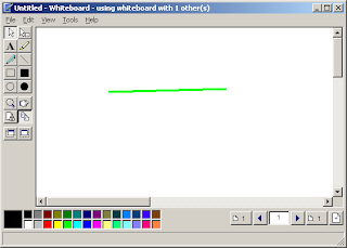
- Menggambar dengan Whiteboard.
- Berkolaborasi dengan user lain untuk mengedit apa-apa yang ada pada program yang kita share (misalnya, kita mengijinkan user lain untuk mengedit file MS Word yang sedang kita buka & share)

Mengkonfigurasi NetMeeting
Untuk memulai chat dengan program ini, maka kita harus menyeting dahulu dengan membuka file conf.exe terlebih dahulu. pada tampilan konfigurasi, lakukan sebagai berikut :
1. Pada tampilan awal tekan Next.

2. Selanjutnya isi data Anda, lalu tekan Next.

3. Centang seperti pada gambar, lalu tekan Next.

4. Pilih koneksi, sebagai contoh Local Area Network (misalnya untuk chatting di lab sekolah, seperti pengalaman penulis (Mbah Rudi)), lalu tekan Next.

5. Centang yang diinginkan untuk membuat shortcut di Desktop atau Quick Launch, lalu tekan Next.

6. Selanjutnya jika sound card Anda rusak atau tidak ada sound card, maka akan seperti pada gambar, tekan Finish untuk mengakhiri .

7. Jika sound card berfungsi ,lanjutkan dengan Audio Tuning Wizard seperti berikut:
a. Keluarkan dulu program yang berhubungan dengan sound card (recording, playing audio/video), lalu tekan Next.

b. Pilih device untuk recording dan playbacknya, lalu tekan Next.

c. Atur volume playback dan jika ingin mengetes suara di speaker atau earphone klik Test, lalu tekan Next.

d. Selanjutnya Anda diminta untuk mengatur volume recording. Untuk mengetes apakah mic berfungsi cobalah baca text di bawah tulisan "Please read the following text into your microphone:", lalu tekan Next.

e. Akhiri Audio Tuning Wizard dengan menekan Finish.


Memulai Chat dengan NetMeeting
Setelah selesai kita meng-konfigurasi, maka selanjutnya kita memulai chat dengan NeMeeting. Caranya :
1. Klik ikon gambar telepon untuk memanggil host lain yang juga sudah dikonfigurasi.Lalu isi pada To alamat IP atau nama host yang akan dipanggil, misalnya 192.168.1.8 (alamat IP) atau komp8 (nama host), lalu tekan Call.
 
2. Setelah itu tunggu respon dari komputer yang dipanggil mengklik Accept, sehingga muncul gambar di bawahnya. Agar komputer kita secara otomatis merespon panggilan, maka kita perlu mengklik File > Automatically Accept Calls.


3. Untuk memulai chat dengan teks tekan tombol dgn ikon balon kata. Lalu pilih user yang kita ajak ngobrol apakah semua orang yang terhubung atau khusus satu orang saja.
    
Untuk men-share program yang kita jalankan klik tombol Share Program dgn ikon jendela tangan. Pilih program yang ingin disharing dan klik Share dan bila ingin mengijinkan user lain mengedit tekan Allow Control, serta Prevent Control untuk menghentikan.
  

Untuk menggambar untuk ditampilkan dalam chat klik tombol Whiteboard.
  
Untuk mengirim file klik File Transfer. Tentukan file yang akan dikirim ke host/user lain dgn mengklik Add Files, lalu pilih user yang akan dikirimi dan tekan Send Files utk mengirim file tersebut. Pada PC host penerima file akan dialog Transfer Complete.


Salah satu kelebihan NetMeeting adalah Remote Desktop Sharing yang mengijinkan user lain juga bisa mengontrol suatu host seperti yg kita lakukan.


Mengubah Setting NetMeeting
Mungkin bila seseorang juga ingin menggunakan komputer yg kita gunakan untuk chat dgn NetMeeting dan mereka ingin settingan yang berbeda, maka mereka harus mengikuti langkah2 sbb:
1. Klik menu Tools > Options...

2. Pada tab General dapat diubah setting adalah tentang informasi pribadi, bandwidth, menjadikan NetMeeting program start (klik Run NetMeeting in the background when windows start), dsb.

3. Pada tab Security untuk setting keamanan saat chatting (incoming dan outgoing)

4. Pada tab Video merupakan setting untuk video conference.

Setelah selesai mengubah settingan, klik tombol OK.

Mengakhiri Chat NetMeeting
Bila kita sudah merasa bosan untuk chatting dgn NetMeeting, tekan tombol End Calls.

All